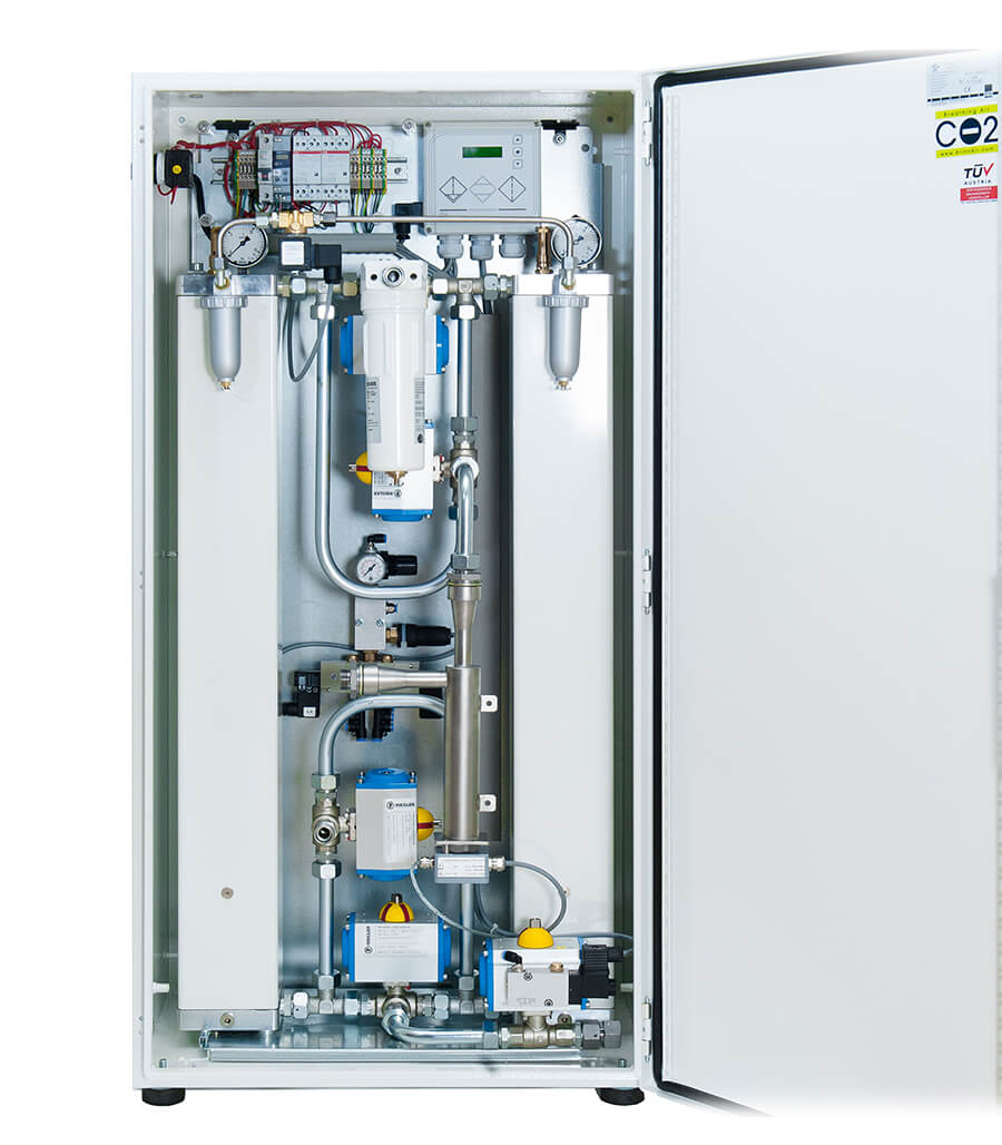
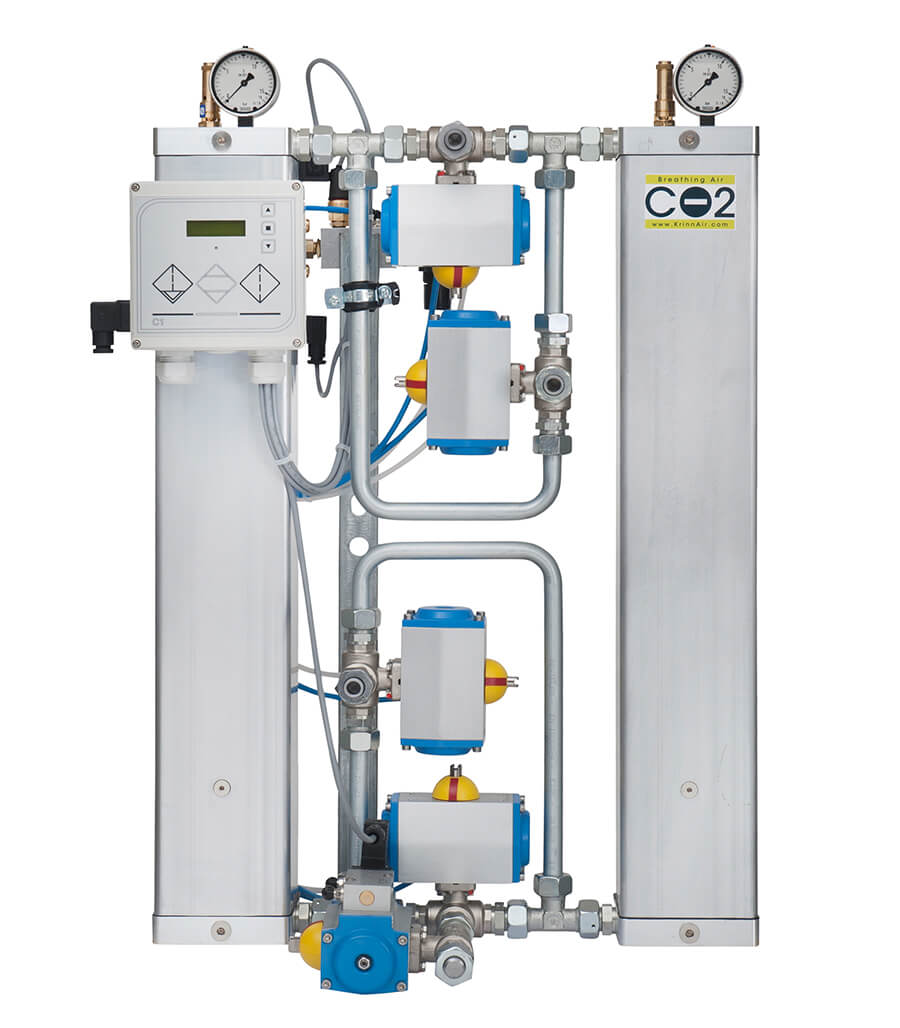
The fully-automated, fully wired and encased CO2 compact system features a defined mode of operation that was not technically possible in the past. The combination of CO2 adsorption and regeneration by supplying nitrogen (available as a by-product of NITROX membrane systems) in particular is an innovation in breathing air generation.
Nitrogen is heated using a compressed air heater and is used for regeneration and drying of the desiccant.
The KrinnAir CO2 Reducer ensures extremely reliable CO2 reduction and drying of compressed air.
The result: an increase in the overall efficiency of NITROX generation while increasing the efficiency and service life of your NITROX membrane.
An integrated particle filter means you can look forward to a service life of up to 500 operating hours. The filter is validated and certified according to quality standard ISO 12.500-1:2007.
With the stand-alone version, this KrinnAir CO2 reduction system is universally useable. The CO2 Reducer can be connected using three flexible hoses.


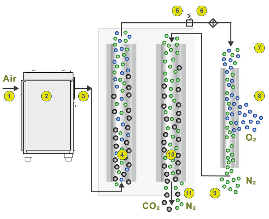
| 1. Compressed air inlet: wet and oily | 6. Compressed air heating |
| 2. Compressed air preparation: drying and filtration | 7. NITROX membrane |
| 3. Compressed air outlet: dry and oil-free | 8. NITROX connection, CO2 reduced |
| 4. CO2 filtration | 9. Nitrogen outlet |
| 5. Pressure reduction | 10. CO2 regeneration |
| 11. N2 / CO2 exhaust |
The pre-compressed air flows under pressure of 7 to 10 bar through the compressed air inlet (1) into the preparation system (2). The compressed air is dried and freed of oil. At the compressed air outlet (3), dry, oil-free compressed air is made available for CO2 processing and NITROX production.
The purified compressed air flows upwards through a container filled with desiccants (4). The drying agents are sufficiently sized to bind to the CO2 and thus adsorb the CO2 over a defined period of time. In parallel, regeneration takes place in the counter-flow of the second desiccant container (10). This is done using nitrogen (about 85%) that is available as residual gas from the NITROX oxygen membrane (9).
Before entering the NITROX membrane (7), the pressure is reduced (5) and the compressed air is heated (6). In the NITROX membrane, oxygen (8) and nitrogen (9) are separated within the hollow fibre membrane to a specific level in order to produce the desired NITROX breathing gas mixture according to DIN EN 12021.
In the final step, the residual nitrogen cleans the CO2-saturated desiccant. With a low residual pressure, the CO2 is reclaimed from the desiccant and discharged through the sound-suppressed exhaust (11).
The system can be integrated into any NITROX system and can be added at any time!
| Model | CO2-7,5 | CO2-11 | CO2-15 |
| CO2 input max. | 2000 ppm | ||
| CO2 output max. | 500 ppm | ||
| Nitrox | 21% - 40% | 21% - 40% | 21% - 40% |
| Volume delivered | 200 – 320 litre/min | 300 – 450 litre/min | 450 – 600 litre/min |
| Volume flow | 1100 litre/min | 1650 litre/min | 2500 litre/min |
| Operating pressure | 7 – 10 bar | 7 – 10 bar | 7 – 10 bar |
| Electrical connection | 230V/50Hz | 230V/50Hz | 230V/50Hz |
| Power consumption | 0,1 KW | 0,1 KW | 0,1 KW |
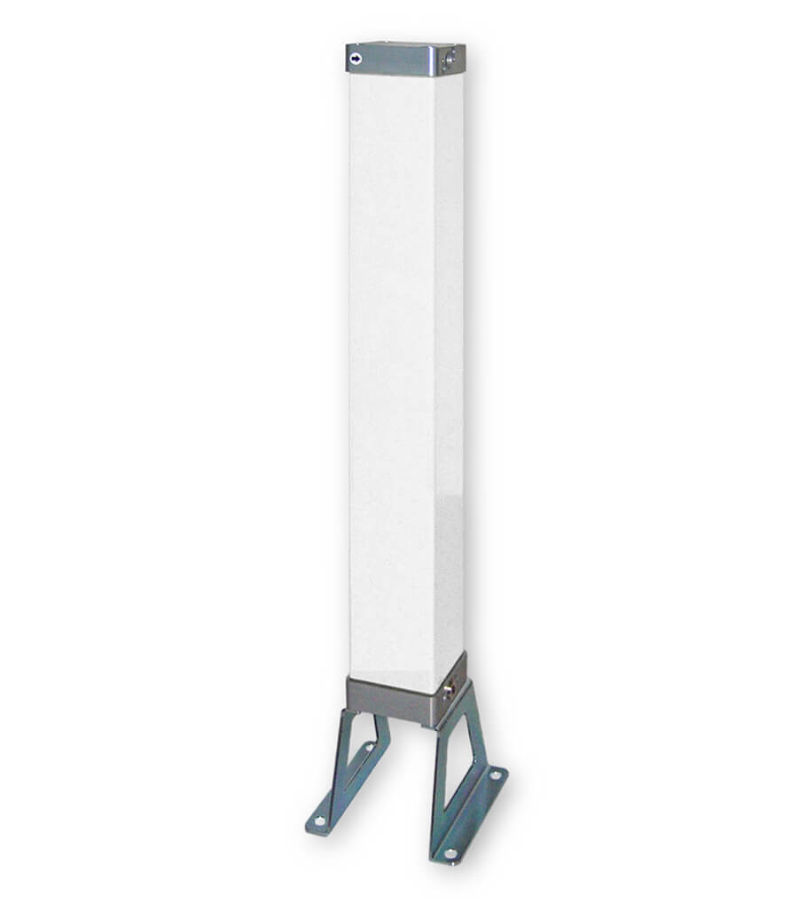
After CO2 reduction, the compressed air passes through a third container. Here carbon monoxide (CO) is oxidised by a catalyst bed and safely removed. The downstream fine-mesh filter retains any particles. The additional module is mounted laterally onto the CO2 Reducer and can be retrofitted at any time.
| Model | CO-7,5 | CO-11 | CO-15 |
| CO output max. | < 5 ppm | ||
| Nitrox | 21% - 40% | 21% - 40% | 21% - 40% |
| Volume delivered | 200 – 320 litre/min | 300 – 450 litre/min | 460 – 600 litre/min |
| Volume flow | 1100 litre/min | 1650 litre/min | 2500 litre/min |
| Operating pressure | 7 – 10 bar | 7 – 10 bar | 7 – 10 bar |
